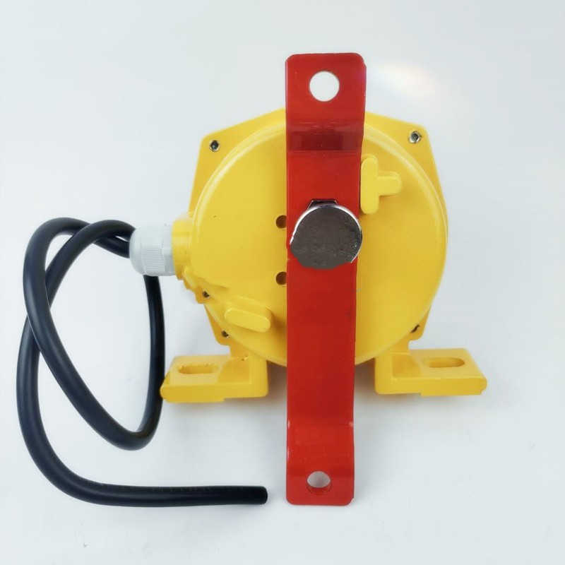
LSKG/I Rope Switch LPS-H-C-ALSKG-I
LSKG/I Rope Switch LSKG/I Rope Switch LPS-H-C-A
- LSKG/I Rope Switch LPS-H-C-A
- ZHUOXIN
- 24-380v
- IP65
- TT, Paypal, Credit card, Western union
- +86-15163766288
- LSKG/I Rope Switch LSKG/I Rope Switch LPS-H-C-A
Description

LSKG/I Rope Switch LSKG-IYHFLS-I; LSKG/I Rope Switch LPS-H-C-A
. The main parameters are shown in the table below. Model: Action Angle Limit Angle Action Force (Kg) Output Method: Load Current Reset Method Reliability Weight (Kg) Normally Open and Normally Closed JHLS-Z Type 15 ° 60 ° 101110A Automatic ≥ 106 Times 1.5 JHLS-S Type 15 ° 60 ° 101110A Manual
IV. Structural Features:
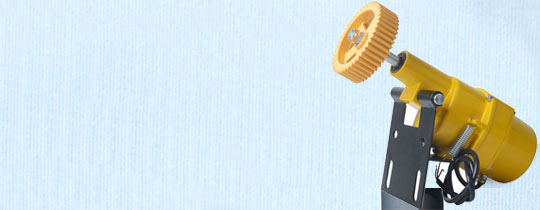
1. This product adopts an aluminum alloy cast shell, with high strength and light weight. 2. The shell protection level reaches IP65 and can work for a long time in harsh environments. 3. This product has sensitive movements, high stability, and reliable performance. The external structure is shown in Figures 1 and 2. 5、 Working principle: When an emergency occurs at the site of a tape conveyor, the steel wire rope tied to the swing arm can be pulled to rotate the swing arm, which drives the internal cam of the conveyor and senses the micro switch, issuing a shutdown signal. 6、 Installation and adjustment: This product is generally installed on two racks along the conveyor belt. Please refer to Figure 3 for details. 1. Fix the rope switch on the bracket. 2. The distance between the two machines is 25-30m, and a steel wire rope with a diameter of 4mm is used for connection. The tension should be moderate. In order to reduce the impact of the weight of the steel wire rope on the switch and cause misoperation, a support ring is welded to the frame every 3 meters to support the steel wire rope and ensure its normal operation< 7. Precautions for Product Installation and Use: 1. The product casing is equipped with a grounding terminal, and users must reliably ground it during installation and use. 2. There should be no toxic gases that corrode aluminum alloys on the installation site. 3. The maintenance of the product must be carried out in a safe place or only when it is confirmed on site that there is no combustible dust present. 4. The shell of the pull cord switch must be kept clean, and the thickness of dust accumulation should not exceed 3mm. Wiring diagram RPLS series bidirectional balance rope switch overview: ● This machine is used for emergency shutdown in case of belt conveyor failure. When an emergency occurs at the tape conveying site, the steel wire rope tied to the lifting ear can be pulled to activate the sliding block and switch inside the machine, issuing a shutdown signal. The manual switch comes with a self locking mechanism, and can only be reset by lifting the upper limit lever after troubleshooting<
Operating environment conditions: ● Environmental temperature: -30 ℃~70 ℃ Relative humidity not exceeding 85%
Usage and installation ● Balanced switch installation on the fixed bracket of the rack.. Tie the steel wire rope to the pull rings at both ends, with each side of the rope not exceeding 40m (shortened when there is a slope). The tension rope pressure should be appropriate to ensure reliable reset of the switch. The pull rope is set in a parallel direction, with a lifting ring added every 10 meters. SHRPLS-ZSHRPLS-S Outline Drawing JZQ-J25N (W); JZQ-J20N(W) JZQ-J15N(W) JZQ-J10N(W) CJZQ-F65L CJZQ-F50L CJZQ-F40L DBW10B 4WEH16E 4WEH16G 4WEH16J 4WEH16D 4WE10G 4WE10H 4WE10E 4WE10J 4WE10Y 4WE10C 4WE10D 4WE10B 4WE10A 4WE6E 4WE6Y 4WE6C 4WE6D 4WE6B 4WE6A DSG-03-3C-AC22 DSG-03-3C-DC24 DSG-03-2B-AC22
Tags
Get the latest price? We'll respond as soon as possible(within 12 hours)

