


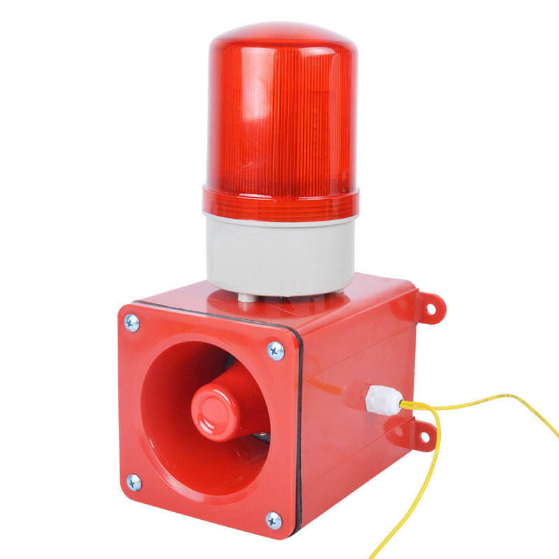
Electronic Alarm QYB200-A Strong Magnet Installation STSG-01
Electronic alarm QYB200-A strong magnet installation sound and light alarm (also known as sound and light alarm) is an alarm signal device used in dangerous places to send warning signals to people through sound and various lights. Explosion proof sound and light alarm is suitable for installation in explosive gas environments containing Class IIC T6 temperature group. It can also be used in Zone 1 and Zone 2 explosion-proof areas with explosion-proof requirements in industries such as petroleum and chemical industry. It can also be used outdoors or outdoors. So, next, the editor will introduce the precautions for using sound and light alarms and the working principle of sound and light alarms.
- Electronic alarm QYB200-A strong magnet installation
- ZHUOXIN
- 24-380v
- IP65
- TT, Paypal, Credit card, Western union
- +86-15163766288
- Electronic alarm QYB200-A strong magnet installation sound and light alarm (also known as sound and light alarm) is an alarm signal device used in dangerous places to send warning signals to people through sound and various lights. Explosion proof sound and light alarm is suitable for installation in explosive gas environments containing Class IIC T6 temperature group. It can also be used in Zone 1 and Zone 2 explosion-proof areas with explosion-proof requirements in industries such as petroleum and chemical industry. It can also be used outdoors or outdoors. So, next, the editor will introduce the precautions for using sound and light alarms and the working principle of sound and light alarms.
Description

Electronic Alarm QYB200-A Strong Magnet Installation Electronic Alarm QYB200-A Strong Magnet Installation Product Introduction Sound and Light Alarm (also known as Sound and Light Alarm Signal) is an alarm signal device used in dangerous places to send warning signals to people through sound and various lights. Explosion proof sound and light alarm is suitable for installation in explosive gas environments containing Class IIC T6 temperature group. It can also be used in Zone 1 and Zone 2 explosion-proof areas with explosion-proof requirements in industries such as petroleum and chemical industry. It can also be used outdoors or outdoors. Non coding type can be used in conjunction with fire alarm controllers from any domestic or foreign manufacturer. When accidents or emergencies such as fires occur at the production site, the control signal sent by the fire alarm controller activates the sound and light alarm circuit, emits sound and light alarm signals, and completes the alarm purpose. It can also be used in conjunction with manual alarm buttons to achieve simple sound and light alarm purposes. Explosion proof products must meet the requirements of the GB3836 series standard (GB3836.1-2000 "General Requirements for Explosion proof Electrical Equipment for Explosive Environments" and GB3836.2-2000 "Explosion proof Electrical Equipment for Explosive Environments" d "standard), and have been identified and obtained an explosion proof certificate by a testing agency. The alarm shell is made of all stainless steel, the lamp shell has strong impact resistance, 180 clear and visible ultra high brightness LED light emitting tubes, equipped with * buzzers, which have the characteristics of stable operation, long service life, low power consumption, and are not affected by pollutants and water. Installation requirements: 1. Fire sound and light alarms should be installed at the safety exit of each fire compartment, and their position should be located near the stairs in the corridors of each floor. At the exit. 2. For protected objects with multiple alarm areas, it is advisable to use fire sound alarms with voice prompts, and the voice should be synchronized. 3. When multiple fire sound alarms are installed in the same building, they should be able to start and stop all fire sound alarms simultaneously. [1] Technical parameters Working voltage AC220V/AC380V/AC24V/AC36V/AC110V/DC24V (special voltage can be customized) Power frequency 50Hz 60Hz Power 6W Tone A/B/E/D/Y/L/F/Voice (optional) Sound level 106dB Color red, yellow, green (optional) Warning method Sound and light
Working temperature -30 ℃ -70 ℃ Protection level IP65 Working humidity 10% -95% (non condensing) Reference weight 2. 7kg material shell: aluminum alloy lampshade: PC Installation method: The sound and light alarm is composed of a detector and an alarm control host. It is widely used in the petrochemical industry where toxic gases exist, such as petroleum, gas, chemical, and oil depots. It is used to detect leaks in indoor and outdoor hazardous areas and is an important instrument to ensure production and personal safety. When toxic gases are present in the tested area, the detector converts the gas signal into a voltage signal or a current signal and transmits it to the alarm instrument. The instrument displays the percentage concentration value of the lower explosive limit of the toxic gas. When the concentration of toxic gases exceeds the alarm set value, an audible and visual alarm signal will sound, and the on duty personnel will take safety measures in a timely manner to avoid combustion and explosion accidents. 1. Precautions for application: Once the fixed installation of the sound and light alarm is in place, its position is not easily changed. The following points should be considered when applying it specifically. (1) Identify the possible leakage points of the device to be monitored, analyze their leakage pressure, direction, and other factors, and draw a distribution map of probe positions. According to the severity of the leakage, it is divided into three levels: I, II, and III. (2) Based on specific factors such as airflow direction and wind direction in the location, determine the direction of toxic gas leakage when a large amount of leakage occurs. (3) Based on the density of the leaked gas (greater than or less than air), combined with the trend of air flow, a three-dimensional flow trend chart of the leak is synthesized, and an initial point setting scheme is made at the downstream position of its flow. (4) Study whether the leakage state at the leakage point is micro leakage or jet like. If it is a minor leak, the location of the point should be closer to the leak point. If it is a jet leakage, it should be slightly away from the leakage point. Based on these conditions, a final site plan for zui has been formulated. In this way, the quantity and variety that need to be purchased can be estimated. (5) For places with significant toxic gas leaks, according to relevant regulations, a detection point should be set up every 10-20 meters apart. For unmanned small and discontinuous pump rooms, attention should be paid to the possibility of toxic gas leakage, and a detector should generally be installed at the lower air outlet. (6) For places with hydrogen leaks, detectors should be installed on the plane above the leak point. (7) For media with a gas density greater than air, the detector should be installed on the lower plane below the leakage point, and attention should be paid to the characteristics of the surrounding environment. Special attention should be paid to the setting of safety monitoring points for places prone to the accumulation of toxic gases. (8) For open environments where toxic gases diffuse and escape, if there is a lack of good ventilation conditions, it is also easy to make the toxic gas content in the air of a certain area close to or reach the lower explosive limit concentration. These are safety monitoring points that cannot be ignored. According to the analysis of the on-site accident, more than half of it was caused by incorrect installation and calibration. Therefore, it is necessary to introduce the precautions for correct installation and calibration to reduce malfunctions. Installation precautions (1) The alarm probe mainly contacts the detection element of the combustion gas sensor, consisting of a spherical coil wrapped with aluminum oxide and adhesive on the platinum wire coil, with rare metals such as platinum and palladium attached to its outer surface. Therefore, be careful during installation to avoid damaging the probe. The sound and light alarm should have at least an audible device without a probe. (2) The installation height of the alarm should generally be above 180cm to facilitate daily maintenance by maintenance personnel. (3) The alarm is a safety instrument with sound and light display functions, and should be installed in a place that is easy for workers to see and hear, in order to timely eliminate hidden dangers. (4) There should be no strong electromagnetic fields (such as high-power motors and transformers) around the alarm that may affect the operation of the instrument. (5) The installation position of indoor probes should also vary depending on the density of the measured gas. When the density of the measured gas is less than the air density, the probe should be installed 30cm away from the roof in a downward direction; On the contrary, the probe should be installed 30cm above the ground in an upward direction. The wiring diagram for the construction of the sound and light alarm uses a three core shielded wire to connect the controller to the detector (note: the single core wire diameter is not less than 0.75mm national standard wire, depending on the actual distance), and the shielding layer is connected to the controller casing and reliably grounded. When using RVV cables, metal pipes should be threaded and reliably grounded. Refer to the wiring diagram of the controller and detector, connect the controller of the sound and light alarm to the corresponding terminals of the detector. Wiring method: 1. Connect the input controller terminal to the detector terminal accordingly; 2. Connection between output terminals and linkage equipment; 3. When inductive devices such as exhaust fans meet the condition of 5A/220VAV or less, they can be directly connected to the output terminal. However, it is advisable to avoid the load equipment being directly connected to the output terminal. When the load equipment is greater than 5A/220VAV, an external adapter device must be connected; 5. The controller and detector should ensure reliable grounding; sixWhen performing various installation operations, it is necessary to turn off the power first, otherwise it may burn out the host< br/>
Working temperature -30 ℃ -70 ℃ Protection level IP65 Working humidity 10% -95% (non condensing) Reference weight 2. 7kg material shell: aluminum alloy lampshade: PC Installation method: The sound and light alarm is composed of a detector and an alarm control host. It is widely used in the petrochemical industry where toxic gases exist, such as petroleum, gas, chemical, and oil depots. It is used to detect leaks in indoor and outdoor hazardous areas and is an important instrument to ensure production and personal safety. When toxic gases are present in the tested area, the detector converts the gas signal into a voltage signal or a current signal and transmits it to the alarm instrument. The instrument displays the percentage concentration value of the lower explosive limit of the toxic gas. When the concentration of toxic gases exceeds the alarm set value, an audible and visual alarm signal will sound, and the on duty personnel will take safety measures in a timely manner to avoid combustion and explosion accidents. 1. Precautions for application: Once the fixed installation of the sound and light alarm is in place, its position is not easily changed. The following points should be considered when applying it specifically. (1) Identify the possible leakage points of the device to be monitored, analyze their leakage pressure, direction, and other factors, and draw a distribution map of probe positions. According to the severity of the leakage, it is divided into three levels: I, II, and III. (2) Based on specific factors such as airflow direction and wind direction in the location, determine the direction of toxic gas leakage when a large amount of leakage occurs. (3) Based on the density of the leaked gas (greater than or less than air), combined with the trend of air flow, a three-dimensional flow trend chart of the leak is synthesized, and an initial point setting scheme is made at the downstream position of its flow. (4) Study whether the leakage state at the leakage point is micro leakage or jet like. If it is a minor leak, the location of the point should be closer to the leak point. If it is a jet leakage, it should be slightly away from the leakage point. Based on these conditions, a final site plan for zui has been formulated. In this way, the quantity and variety that need to be purchased can be estimated. (5) For places with significant toxic gas leaks, according to relevant regulations, a detection point should be set up every 10-20 meters apart. For unmanned small and discontinuous pump rooms, attention should be paid to the possibility of toxic gas leakage, and a detector should generally be installed at the lower air outlet. (6) For places with hydrogen leaks, detectors should be installed on the plane above the leak point. (7) For media with a gas density greater than air, the detector should be installed on the lower plane below the leakage point, and attention should be paid to the characteristics of the surrounding environment. Special attention should be paid to the setting of safety monitoring points for places prone to the accumulation of toxic gases. (8) For open environments where toxic gases diffuse and escape, if there is a lack of good ventilation conditions, it is also easy to make the toxic gas content in the air of a certain area close to or reach the lower explosive limit concentration. These are safety monitoring points that cannot be ignored. According to the analysis of the on-site accident, more than half of it was caused by incorrect installation and calibration. Therefore, it is necessary to introduce the precautions for correct installation and calibration to reduce malfunctions. Installation precautions (1) The alarm probe mainly contacts the detection element of the combustion gas sensor, consisting of a spherical coil wrapped with aluminum oxide and adhesive on the platinum wire coil, with rare metals such as platinum and palladium attached to its outer surface. Therefore, be careful during installation to avoid damaging the probe. The sound and light alarm should have at least an audible device without a probe. (2) The installation height of the alarm should generally be above 180cm to facilitate daily maintenance by maintenance personnel. (3) The alarm is a safety instrument with sound and light display functions, and should be installed in a place that is easy for workers to see and hear, in order to timely eliminate hidden dangers. (4) There should be no strong electromagnetic fields (such as high-power motors and transformers) around the alarm that may affect the operation of the instrument. (5) The installation position of indoor probes should also vary depending on the density of the measured gas. When the density of the measured gas is less than the air density, the probe should be installed 30cm away from the roof in a downward direction; On the contrary, the probe should be installed 30cm above the ground in an upward direction. The wiring diagram for the construction of the sound and light alarm uses a three core shielded wire to connect the controller to the detector (note: the single core wire diameter is not less than 0.75mm national standard wire, depending on the actual distance), and the shielding layer is connected to the controller casing and reliably grounded. When using RVV cables, metal pipes should be threaded and reliably grounded. Refer to the wiring diagram of the controller and detector, connect the controller of the sound and light alarm to the corresponding terminals of the detector. Wiring method: 1. Connect the input controller terminal to the detector terminal accordingly; 2. Connection between output terminals and linkage equipment; 3. When inductive devices such as exhaust fans meet the condition of 5A/220VAV or less, they can be directly connected to the output terminal. However, it is advisable to avoid the load equipment being directly connected to the output terminal. When the load equipment is greater than 5A/220VAV, an external adapter device must be connected; 5. The controller and detector should ensure reliable grounding; sixWhen performing various installation operations, it is necessary to turn off the power first, otherwise it may burn out the host< br/>
Tags
Get the latest price? We'll respond as soon as possible(within 12 hours)