

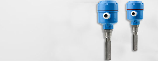


NJK-3130LA Magnetoelectric Sensor Cylinder Travel Switch Available
The NJK-3130LA magnetic electric sensor cylinder stroke switch can be usedThe NJK series magnetic electric sensors can be used to determine the position of pneumatic, hydraulic, cylinder, and piston pumps on equipment such as valve positions, hydraulic devices, oil guns, and soot blowers. They can also be used as limit switches and do not require a separate power supply to function normally.
- ZHUOXIN
- 24v-110v-220v-380v
- IP65
- TT, Paypal, Credit card, Western union
- +86-15163766288
- The NJK-3130LA magnetic electric sensor cylinder stroke switch can be usedThe NJK series magnetic electric sensors can be used to determine the position of pneumatic, hydraulic, cylinder, and piston pumps on equipment such as valve positions, hydraulic devices, oil guns, and soot blowers. They can also be used as limit switches and do not require a separate power supply to function normally.
Description

The NJK-3130LA magnetic electric sensor cylinder stroke switch can be used for measuring the position of pneumatic, hydraulic, cylinder, and piston pumps on equipment such as valve positions, hydraulic devices, oil guns, and soot blowers. It can also be used as a limit switch and does not require a separate power supply to function properly. Our company's NJK series magneto electric sensors can also be used as limit switches for measuring the position of pneumatic, hydraulic, cylinder, and piston pumps on equipment such as valve positions, hydraulic devices, oil guns, and soot blowers, without the need for a separate power supply to function properly. 2、 Characteristics of Performance; The NJK-3130LA magneto electric sensor cylinder stroke switch can generate a magnetic field effect when the magnetic target approaches the sensor, causing the internal contact output of the magneto electric sensor to close and amplify the output switch signal. Compared with inductive sensors, it has the following advantages: it can be installed in metal, can be tightly installed side by side, and can pass through the metal for detection. The detection distance varies with the strength of the magnetic field of the object being tested. 3、 Specifications, models, and external dimensions: normally open NJK-2316LA, normally closed NJK-2316LB, normally open NJK-2608LA, normally closed NJK-2608LB, normally open NJK-2919LA, normally closed NJK-2919LB, normally open NJK-2607LA, normally closed NJK-2607LB, normally open NJK-2612LA, normally closed NJK-2612LB, normally open NJK-3029LA, normally closed NJK-3029LB, normally open NJK-3130LA, normally closed NJK-3130LB, normally open NJK-3410LA. Closed type NJK-3410LB normally open type NJK-3518LA normally closed type NJK-3518LB normally open type NJK-3312LA normally closed type NJK-3312LB normally open type NJK-3416LA normally closed type NJK-3416LB normally open type NJK-3618LA normally closed type NJK-3618LB magnetoelectric sensor uses the principle of electromagnetic induction to convert the input motion speed into an induced electromotive force output, and is an active sensor. It does not require an auxiliary power supply and can convert the mechanical energy of the tested object into a number that is easy to measure. Moreover, it has bidirectional conversion characteristics, and its inverse conversion effect can be used to form force (moment) generators and electromagnetic oscillators. Sometimes magneto electric sensors are also known as electric or inductive sensors; It only performs dynamic measurements. Due to its large output power, the matching circuit is relatively simple; Zero position and stable performance; The working frequency band is generally between 10 and 1000Hz. The composition and characteristics of a magneto electric sensor. The experimental technical parameters of a magneto electric sensor. The application of a magneto electric sensor. The composition of a magneto electric sensor includes a magnetic circuit system, coil 1, and magnetic circuit system, which generate a constant DC magnetic field. In order to reduce the volume of sensors, * magnets are generally used; 2. The coil generates induced electromotive force by cutting magnetic field lines through its motion. As a complete magneto electric sensor, in addition to the magnetic circuit system and coil, there are also some components such as a shell, support, damper, wiring device, etc. The principle and characteristics of a magneto electric sensor (1) Working principle The working principle of a magneto electric sensor is shown in Figure 1, which mainly consists of a rotating contact wheel (a divided gear plate with multiple or missing teeth) and a relatively stationary induction coil. When the diesel engine is running, the gap between the contact wheel and the sensor changes periodically, and the magnetic flux also changes with the same period, thereby inducing a voltage signal that is approximately a sine wave in the coil. The output characteristics of Shandong Zhuoxin (2) can be inferred from the working principle of a magneto electric sensor. The frequency of the AC voltage signal generated by it is proportional to the gear speed and number of teeth. When the number of teeth is determined, the voltage frequency output by the sensor coil is proportional to the speed of the gear, and its relationship is as follows: n is the engine speed, r/s; z is the number of teeth evenly divided by the contact wheel; F is the output signal frequency of the magneto electric sensor, Hz. The output voltage of the magneto electric sensor is not only related to the gap between the sensor and the contact wheel; Related, and also related to n. In order to design a reasonable signal processing module for magneto electric sensors, the output voltage characteristics of the sensors were measured through a large number of experiments under different and n conditions. Figure 2 shows the relationship between the peak voltage output of the 7 X sensor and under different n conditions; Figure 3 shows the relationship between the peak voltage output of the 7 X sensor and n under different conditions. The peak voltage signal characteristics of the 48 X sensor output are also the same. From the graph, it can be seen that under the same conditions, the peak voltage output by the sensor increases with the increase of n; Under the same n conditions, the smaller the value, the higher the peak output voltage. From this, the output peak voltage characteristic of the sensor can be fitted as follows: V is the sensor output peak voltage, V; n is the engine speed, r/s; and is the gap between the sensor and the contact wheel, mm; K is a parameter related to the sensor. Experiment 1, Experimental Principle of Magnetoelectric Sensor: Magnetoelectric sensor is a type of sensor that can convert non electric changes into induced electromotive force, so it is also known as an induction sensor. According to the law of electromagnetic induction,ω The magnitude of the induced electromotive force e in a coil depends on the magnetic flux passing through the coil? The rate of change: A Hall sensor is a type of magneto electric sensor that utilizes the Hall effect of a material. The sensor is composed of a gradient magnetic field composed of two circular magnetic steels and a Hall element located in the magnetic field. When the Hall element is energized with a constant current, the Hall element has a potential output. When a Hall element moves up and down in a gradient magnetic field, the output Hall potential V depends on its displacement X in the magnetic field. Therefore, measuring the magnitude of the Hall potential can determine the static displacement of the Hall element. 2、 Required components for the experiment: DC stabilized power supply, bridge, Hall sensor, differential amplifier, voltmeter, and micrometer head. 3、 Experimental steps: 1. Understand the structure of the Hall sensor and its position on the experimental instrument, and become familiar with the symbols of the Hall sensor on the experimental panel. The Hall plate is installed on the vibrating disc of the experimental instrument, and two semi-circular * magnetic steels are fixed on the top plate of the experimental instrument, forming a Hall type sensor. 2. Zero the differential amplifier. Afterwards, turn off the power and adjust the amplifier gain to * * * small. 3. Install the micrometer head and adjust it to drive the displacement of the vibration table, so that the Hall plate is placed in the center position of the semi-circular magnetic steel. Turn on the power, adjust W or fine tune the micrometer head to indicate a voltage of 0. 4. Starting from this, move the micrometer head up and down by 0.5mm each time, record the output data, and fill them in the corresponding tables. nine hundred
Tags
Get the latest price? We'll respond as soon as possible(within 12 hours)